
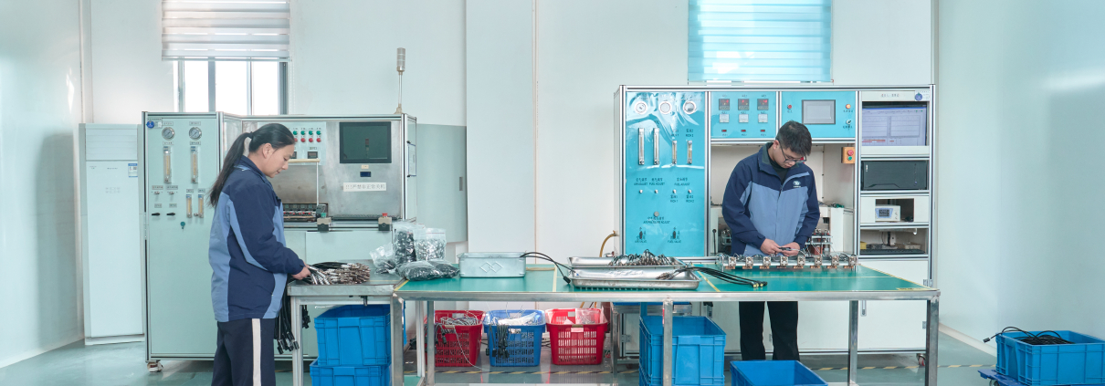
Oxygen Sensor Validation Matrix: From Heater Testing to Vehicle Verification
An oxygen sensor validation matrix is a structured test plan that connects each product requirement to a test method, defined operating conditions, acceptance criteria and recorded evidence. It helps manufacturers and buyers evaluate whether a lambda sensor meets the requirements of its intended vehicle application.
A useful matrix covers mechanical fit, electrical integrity, heater performance, signal characteristics, response time, environmental durability and vehicle compatibility. The test plan must identify the sensor technology, part number, controller and installation position before testing begins.
For aftermarket buyers, the key question is whether the supplier can provide traceable evidence for the specific application being sourced.
Why an oxygen sensor needs more than a basic functional test
A sensor may produce a signal on a laboratory bench while still showing slow activation, signal drift or compatibility problems in a vehicle. A room-temperature electrical check also cannot demonstrate insulation performance at operating temperature.
Validation therefore needs to examine several questions:
- Does the sensor fit the intended installation and connect to the correct circuits?
- Does its heater activate the sensing element under the specified control strategy?
- Does the signal respond correctly under defined gas conditions?
- Does performance remain within agreed limits after durability testing?
- Does the sensor work with the intended vehicle ECU and diagnostics?
Matching a connector and thread is only part of this assessment.
Define the application before building the matrix
Record the OE reference, vehicle model, engine code, applicable production years and upstream or downstream position. Also identify the sensor technology, connector pinout, cable routing, heater control and signal interface.
Narrowband zirconia sensors are evaluated primarily for switching behavior around stoichiometric conditions. Wideband sensors require evaluation of their measurement characteristic with the appropriate control electronics. Other sensor technologies need their own methods.
For example, Bosch documents LSU 4.9 as a heated dual-cell wideband sensor requiring dedicated control electronics. Its pump-current characteristic and controller-generated output must be distinguished when interpreting results.[1]
Acceptance limits should come from the applicable drawing, technical specification or customer-approved requirement. OE benchmarking can support that process, but it does not by itself establish a universal pass/fail standard.
A practical oxygen sensor validation matrix
The following technical overview complements Tianbang’s six-level matrix and explains the evidence behind each validation area. Select the applicable tests and define sample sizes, test severity and limits before execution.
| Validation area | What to evaluate | Conditions to define | Evidence to retain |
|---|---|---|---|
| Identification and fit | Part number, thread, connector, pinout, cable length and installation geometry | Approved drawing and vehicle application | Dimensional report, pinout verification and photographs |
| Electrical integrity | Heater resistance, continuity and unintended short circuits | Measurement temperature, instrument and circuit configuration | Individual readings linked to sample IDs |
| Heater performance | Cold-start activation, current profile and stable operation | Initial temperature, supply profile, PWM/control strategy and current limits | Time-aligned voltage, current and activation traces |
| Insulation resistance | Electrical isolation between heater and specified sensing circuits | Hot/cold state, connected terminals, applied voltage and measurement delay | Leakage current, calculated resistance and setup diagram |
| Narrowband signal | Rich/lean output and switching behavior | Gas composition, flow, temperature and measurement loading | Signal curves against defined gas conditions |
| Wideband characteristic | Pump-current or controller-reported lambda characteristic | Compatible controller, calibration, reference gas and pressure | Multi-point curve and deviations from reference |
| Dynamic response | Lean-to-rich and rich-to-lean response | Gas transition, fixture transport delay and response definition | Raw time traces and calculated response times |
| Signal stability | Repeatability, drift and restart consistency | Test duration, operating points and restart sequence | Repeated measurements and drift records |
| Environmental durability | Thermal cycling, vibration, moisture and sealing performance where applicable | Application-specific profile, mounting, duration and severity | Pre/post-test functional data and inspection results |
| Contamination exposure | Performance after relevant contaminant exposure | Substance, concentration, exposure method and duration | Characteristic and response changes |
| OE comparison | Performance against a correctly identified OE reference | Same fixture, controller, gas, temperature and test sequence | Overlaid curves and documented deviations |
| Vehicle verification | Cold starts, closed-loop behavior, fuel trims and diagnostic compatibility where applicable | Engine condition, ECU version, drive sequence and data channels | Scan logs, operating data and diagnostic results |
This matrix is not a universal test standard. A development programme may need additional mechanical, electrical or endurance tests.
Tianbang’s six-level oxygen sensor validation framework
Tianbang’s validation matrix organises checks into six levels, from basic product integrity to production consistency and traceability. These internal levels describe the validation scope; they are not industry certification grades.
| Level | Validation scope | Main measurements and records |
|---|---|---|
| L1: Basic product integrity | Appearance, critical dimensions, cold heater resistance, continuity, pinout, insulation, sealing and connection strength | Housing and ceramic condition; drawing tolerances; heater resistance at 20–25°C with ambient temperature recorded; circuit identification; insulation between heater, signal circuits and housing; sealing and retention/pull-test results |
| L2: Laboratory performance | Heater performance, operating-point stability, signal characteristic, dynamic response and repeatability | Start-up time; heater voltage/current/resistance curves; operating temperature or internal-resistance target; signal drift; rich/lean transitions and T10/T50/T90 |
| L3: OE benchmarking | Reference-sensor comparison and curve overlays | Matched equipment, gas composition, voltage, temperature, flow and sampling rate; overlaid heater, output and dynamic-response curves |
| L4: Vehicle verification | Cold start, closed-loop operation, idle, acceleration, load and diagnostics | O₂ readiness; closed-loop entry; heater duty; lambda; short- and long-term fuel trims; pending/confirmed DTCs and freeze-frame records; front/rear sensor interaction where applicable |
| L5: Reliability and durability | Environmental and endurance exposure followed by performance reassessment | Applicable high/low-temperature, thermal-shock, vibration, water-resistance, salt-spray, start/stop heating and high-temperature endurance tests; pre/post-test signal curves, T90, heater performance and drift |
| L6: Production consistency and traceability | Process monitoring, abnormal-product segregation and batch records | Online key-parameter checks, statistical process control, first-piece and patrol inspections; serial/batch links to test data, decisions, raw materials and process history |
For wideband sensors, the matrix identifies lambda points of 0.8, 0.9, 1.0, 1.1, 1.3, 1.5 and 1.7 for characteristic evaluation, including pump current, linearity, zero point and slope. Their use must match the sensor’s intended measurement range and test specification. Narrowband evaluation instead addresses rich, stoichiometric and lean behavior, voltage range, switching point and repeatability.
Vehicle diagnostic review includes relevant P013x, P014x, P003x and P005x code families where supported by the application. Code definitions and diagnostic procedures must be checked against the vehicle service information. An oxygen-sensor-related code alone does not establish that the sensor is defective.
Front/rear sensor interaction and emissions assessment are selected according to application risk. Where required, use the relevant regulatory or emissions cycle; ordinary vehicle verification should not be described as emissions certification.
When should each validation test be performed?
100% inspection does not mean every validation test is performed on every sensor. In Tianbang’s matrix, individual products are checked for key manufacturing parameters, batches receive selected performance checks, and new models undergo broader laboratory, OE and vehicle validation. Major material, design or process changes trigger risk-based revalidation.
The schedule below translates the supplied matrix. ● means required or recommended as part of the standard validation scope; ○ means selected by risk assessment or sampling; — means normally not performed at that stage. A filled symbol does not establish that a test has already been completed for a particular SKU.
| Validation item | New model | First batch | Each batch | Each unit | Major change | Complaint / abnormality |
|---|---|---|---|---|---|---|
| Appearance | ● | ● | ● | ● | ○ | ○ |
| Critical dimensions | ● | ● | ○ | ○ | ○ | ○ |
| Cold heater resistance | ● | ● | ● | ● | ● | ● |
| Continuity / pinout | ● | ● | ● | ● | ● | ● |
| Insulation performance | ● | ● | ● | ● | ● | ● |
| Sealing / terminals / harness | ● | ● | ○ | ○ | ○ | ○ |
| Heater performance | ● | ● | ○ | — | ● | ● |
| Operating-point verification | ● | ● | ○ | — | ● | ● |
| Wideband lambda–pump-current curve | ● | ● | ○ | — | ● | ● |
| Narrowband lambda–voltage behavior | ● | ● | ○ | — | ● | ● |
| Dynamic response | ● | ● | ○ | — | ● | ● |
| Repeatability | ● | ○ | ○ | — | ● | ● |
| OE benchmarking | ● | ● | — | — | ● | ● |
| Curve overlays | ● | ● | — | — | ● | ● |
| Cold start / closed loop | ● | ○ | — | — | ○ | ● |
| Idle / acceleration / load | ● | ○ | — | — | ○ | ● |
| DTC verification | ● | ○ | — | — | ○ | ● |
| Front/rear interaction / emissions | ○ | ○ | — | — | ○ | ○ |
| Reliability / durability | ● | — | — | — | ● | ○ |
| Pre/post-durability performance | ● | — | — | — | ● | ○ |
| Production consistency | ● | ● | ● | ● | ● | ● |
| Batch traceability | ● | ● | ● | ● | ● | ● |
The actual execution plan should specify applicable sensor types, sample quantities, acceptance limits and responsible reviewers. Tests marked for every unit do not automatically mean destructive connection-strength testing or full endurance testing on every unit.
For new models, the matrix prioritises comparison with the corresponding OE sample under identical conditions. During series production, its focus shifts to consistency of key parameters and traceability.
Three measurements that need precise definitions
1. Cold-start activation time
Activation time is the elapsed time from a defined starting event to a defined readiness criterion. The report must explain both.
Specify the initial sensor temperature, heater supply or control profile, current limit and readiness threshold. Record heater voltage, current and the relevant sensing measurement on the same time axis.
Two suppliers’ activation times cannot be compared fairly if one starts timing at heater energisation and the other starts at engine cranking, or if they use different readiness criteria. There is no single activation-time limit suitable for every oxygen sensor.
2. Hot insulation resistance
An insulation test must identify the terminals being measured and the sensor’s thermal state. Testing a bare sensing element and testing a finished assembly may involve different accessible connections and leakage paths.
For a defined DC leakage measurement:
Insulation resistance = applied insulation-test voltage / measured leakage current
The applied insulation-test voltage is the voltage across the insulation path under test. It must be distinguished from the voltage used to power the heater.
As an arithmetic example, 13.5 V divided by 13.5 µA equals 1 MΩ. This example is not a universal acceptance limit.
For a hot test, also record the heating procedure, whether heating continues during measurement, and the delay between heater shutdown and measurement. A different delay can produce a different thermal condition.
3. Dynamic response time
Response time describes how quickly the measured output changes after a defined change in gas conditions. Define the output thresholds used for timing, such as 10% to 90% of a specified signal change, where appropriate.
Record both transition directions. Account for gas transport and switching delays in the fixture so that the test distinguishes sensor behavior from test-system behavior.
Warm-up time and gas-response time answer different questions and should appear separately in the report.
How to compare an aftermarket oxygen sensor with OE
Use an authenticated OE reference for the intended application. Record its part number, condition and test history; an aged or unidentified reference can distort the comparison.
Run both sensors using the same test conditions and compatible control electronics. Compare activation, steady-state characteristics, dynamic response, heater behavior and post-durability performance as required by the project.
Report sample size and variation, not only the best result. Where practical, include sensors from more than one production batch.
OE comparison is technical evidence for the conditions tested. It should not be presented as OEM approval or proof of equivalent service life without the corresponding validation.
What buyers should request in a validation report
Ask for a report tied to the proposed part number and application. It should include:
- Sample IDs, batch traceability and the approved specification revision.
- Test methods, equipment identification and calibration status.
- Gas, electrical, thermal and controller conditions.
- Sample counts and the reason for the sampling plan.
- Acceptance limits with their source.
- Individual results, original curves and deviations.
- Pre/post-durability comparison where applicable.
- A conclusion stating the applications and conditions covered.
For failed tests, record containment, root-cause investigation, corrective action and retest evidence. Product or material changes should trigger a review of which validation steps need to be repeated.
Frequently asked questions
What tests should an oxygen sensor validation matrix include?
It should cover fit, electrical integrity, heater performance, insulation, signal characteristics, response, durability and vehicle compatibility. The exact methods and limits depend on sensor technology and the intended application.
Does a heater resistance test prove that an oxygen sensor works correctly?
No. Heater resistance checks one electrical characteristic. It does not demonstrate gas measurement performance, activation time, hot insulation or compatibility with the vehicle ECU.
Is there a universal oxygen sensor response-time standard?
A single limit should not be applied across all oxygen sensor types and applications. A meaningful response-time requirement needs defined gas conditions, temperature, signal thresholds and an agreed specification.
Can narrowband and wideband sensors use the same validation method?
Some mechanical and electrical checks may overlap. Signal validation must reflect the technology: narrowband switching behavior and wideband measurement characteristics require different evaluation.
Does 100% factory inspection replace development validation?
No. Factory inspection screens the measured characteristics of production units. Development validation examines broader performance, durability and application requirements, often using dedicated sample groups.
Why is vehicle testing needed after laboratory testing?
Vehicle testing evaluates the sensor with the actual ECU, heater control, exhaust conditions and diagnostics. Laboratory testing provides repeatable measurements; vehicle testing adds evidence about system integration.
Discuss your oxygen sensor validation requirements with Tianbang
Hubei Tianbang Automotive Electronic Technology Co., Ltd. manufactures emission control sensors and provides information about its production and laboratory controls on its Quality Control page.[2]
When evaluating an oxygen sensor project, send the OE reference, vehicle application, installation position and required test criteria. These details help define the relevant validation scope and the evidence needed for your sourcing decision.
Contact: sales@tb-autoparts.com
Website: www.tb-autoparts.com